How do you size steam pipework & valves for steam applications?
BM Engineering Supplies explains how to size your pipework and valves for steam applications and previews Bürkert’s free – and extremely useful – downloadable Steam Site Guide for steam professionals.
Modern production environments require maintenance teams to be experts in a range of fields. While many areas may be adequately covered, steam equipment can sometimes be overlooked. This can lead to costly breakdowns or repairs, which could be avoided if some basic principles were better understood.
Steam process valves, such as those available from Bürkert, are integral to the steam system and their safe operation. Performance and longevity depend on the proper selection, sizing and position of the steam components that surround them. Failure to employ both the basic fundamentals and appropriate selection of the steam system elements will inevitably result in poor performance and early failure.
How to size a steam pipe
It is widely appreciated that steam velocity is an important factor in the life and maintenance of a steam pipe. As steam velocity is such a practical issue, it could easily form the basis of a sizing method for steam pipes. For relatively short runs (less than 50m), velocities of 15 to 40 m/s are used in saturated steam applications. However, 25m/s is generally adopted as a happy medium. For longer pipe runs, alternative pressure drop methods are normally considered.
An industrial food autoclave condenses 180 kg/h of saturated steam and the steam pressure is 3 barG. Using the example table on page nine of Bürkert’s Steam Site Guide, starting on the left hand side, find the steam pressure required and select the desired velocity. Trace a line horizontally across, until you reach a figure greater than the required 180 kg/h. From there trace a line vertically upwards and simply read off the pipe size, which in this example would be 32mm.
How to size a steam trap
Steam heat exchange applications receive their energy by the action of condensation. When saturated steam comes into contact with a surface at a lower temperature than itself, it condenses and gives some of its energy to the surface. It is vital to know that for every kg of saturated steam condensed in a process, you will create a corresponding kg of condensate.
If an application uses 100kg/h of steam, it will produce 100kg/h of condensate. Sizing the steam trap correctly will ensure that the heat transfer surfaces are free of the lower-energy carrying condensate. Successful condensate removal will help to achieve the best possible plant performance. Should condensate remain in the steam space, it would reduce the available heat transfer area and thus reduce performance.
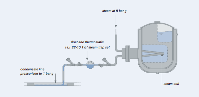
A storage tank with a steam coil is calculated to condense steam at a rate of 4000 kg/h. Steam is supplied at 8 barG and the steam trap discharges into a condensate line pressurised to 1 bar g. The manufacturer of the tank has recommended a float and thermostatic steam trap solution.
Speak to one of BME’s knowledgeable advisers about all your steam equipment requirements today by calling 0141 762 0657 or email sales@bmengineering.co.uk.


